博文

目前显示的是 九月, 2017的博文

Product--RMF69 Shield

图片
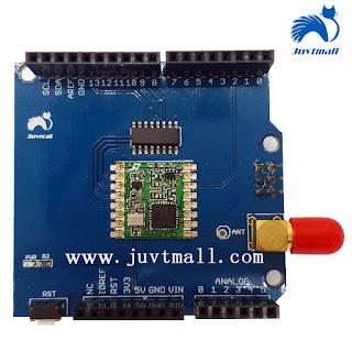
RMF69 Shield-433MHz contains a FSK wireless module, it has the same function that radio frequency transmitter owns, such as receiving and transmitting message. RMF69 Shield-433MHz can totally compatible to Arduino. Features Low consumption More professional ISM band Frequent range from 140 to 960MHz  Totally compatible to Arduino http://juvtmall.com/rfm69-shiled_p0808.html

9. The design of PCB (multiple layer board)--Basic requirement of designing multiple layer PCB VOL1

图片
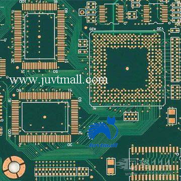
6. Basic requirement of designing multiple layer PCB       Juvtmall  ( a company supply  PCB Prototyping ,  PCBA service  and sell kinds of  components, modules  and so on)  Determine out shape, size, layers. Any plate, there are problems with other structural parts, so the shape and size of the printing plate must be based on the product machine structure. However, in terms of production process, it should be as simple as possible, generally for the long width ratio not too wide of the rectangle, to facilitate assembly, improve production efficiency, lower labor cost. The number of layers must be based on the circuit performance, the size of the plate and the intensity of the line. In the case of PCB multilayer, the application of four layers and six laminates is the most widely used, with four layers as an example, which is two conductor layers (surface and welding surface), a power supply layer and a layer. The layers of the multilayer should be symmetrical

Product--SIM808

图片
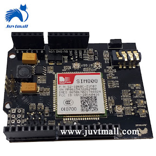
Juvtmall  ( a company supply  PCB Prototyping ,  PCBA service  and sell kinds of  components, modules  and so on)  The SIM808 GPRS/GSM+GPS Shield V1.0 is based on the chip named SIM808, it communicates with Catduino Uno via pins (RX, TX) with GPS data and GPRS data. For the operate voltage could either at 3.3V or 5V, it can be totally compatible to the Arduino. It can be also used to making/answering call, sending/receiving SMS messages and local the position. By the way, SIM GPRS/GSM+GPS Shield V1.0 suppose an SIM card holder at the opposite side. http://juvtmall.com/sim808-btgsmgps-sheild_p0813.html

Products---Simduino

图片
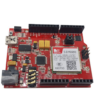
  Juvtmall  ( a company supply  PCB Prototyping ,  PCBA service  and sell kinds of  components, modules  and so on)  Here, you can know the details:  http://juvtmall.com/simduino_p0814.html Contact me: ann@juvtmall.com

8. The design of PCB (multiple layer board)---Method of wring and necessary work

图片
2.  Method of wiring on multiple layers PCB       Juvtmall  ( a company supply  PCB Prototyping ,  PCBA service  and sell kinds of  components, modules  and so on)     Generally, four layers board can be divide into top layer, bottom layer and two internal layer. Internal layer: by command “DESIGN/LAYER STACK MANAGER” use “ADD PLANE” add “INTERNAL PLANE1” and “INTERNAL PLANE2” as VCC and GND in power and GND layer (tip: don’t use “ADD LAYER”, it will add MIDPLAYER, it’s used in multiple layer of signal track), if there are several power layer such as VCC2 or GND layer such as GND2, then use bolder wire or FILL to draw a district on power of GND belongs to PLANE1 or PLANE2,  use PLACE/SPLIT PLANE to make a corresponding district (VCC2 copper and GND2 copper flakes are not present in this area in the same PLANE) tip: different surface layers in the same PLANE and try not to overlap.SPLIT1 and SPLIT2 are overlapped in the same PLANE, and SPLIT2 is inside the SPLIT1, which automatic

A World Without Technology, can you image?

图片

7. The design of PCB(multiple layer board)-- Process of multilayer board

图片
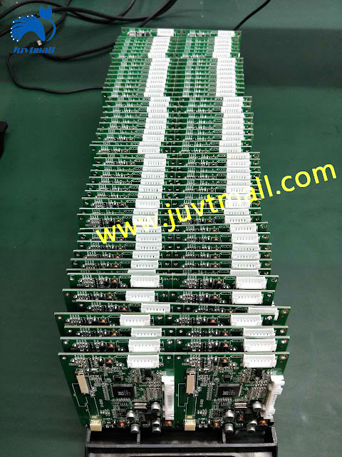
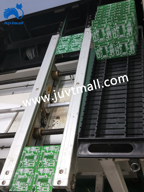
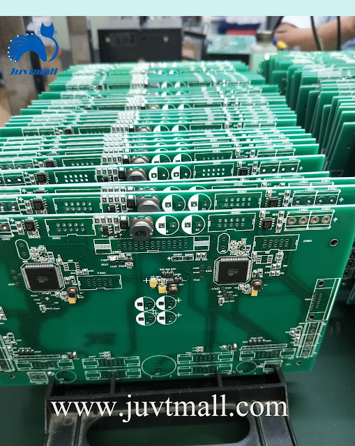
Multiple Layer Board   Juvtmall  ( a company supply  PCB Prototyping ,  PCBA service  and sell kinds of  components, modules  and so on)  PCB Multilayer Board means multilayer board used in electrical product, it involves wild area, such as home appliance, computer accessories, communication, toy, instrument, LED and so on. PCB(printed circuit board) Multilayer Board is consist of track on several layer of insulation substrate and pad, it has two function: conduct every layer ’ s circuit, insult mutual layer. As the develop of SMT, the launch of new SMD (such as QFP, QFN, CSP, BGA), electrical product become more intelligent and smaller. Since HDI is created, the develop these process technology lead the design of PCB to multiple layer, and high density.   1 . Process of multilayer board   1. PCB which has draw the track: Put on the board, acidity deoiling, scanning rinsing, second reflux rinsing, micro etch, scanning rinsing, second reflux rinsing, presoak coppe
6. The design of PCB-- related skills

图片
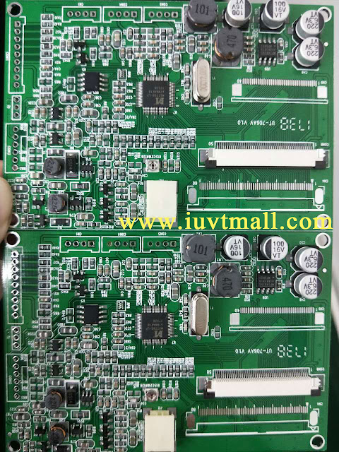
9. PCB design related skills   Juvtmall  ( a company supply  PCB Prototyping ,  PCBA service  and sell kinds of  components, modules  and so on)  PCB design setting technique The PCB design needs to be set different points  in different stages. In the layout phase, the device layout can be used in the large lattice point . For large devices such as IC and non-locating connectors, the lattice site of 50~100mil can be selected for layout, and the grid point of 25mil can be used for the distribution of passive devices such as resistance capacitance and inductance. The precision of the large lattice point is beneficial to the orderliness and beauty of components. PCB layout rules 1. In general , all components shall be decorated on the same side of the boards, only the top-level element too close, set some highly limited and calorific value small devices o n the bottom., such as SMD resistor, SMD capacitors, SMD IC, etc. 2. Under the premise of ensuring electrical pe

5. The design of PCB--design considerations and assembly rules

图片
. PCB design considerations   Juvtmall  ( a company supply  PCB Prototyping ,  PCBA service  and sell kinds of  components, modules  and so on)  (1) avoid setting important signal lines on the edge of PCB, such as clock and reset signal. (2) the distance between the ground wire of the enclosure and the signal line is at least 4mm; keep the length and width of the ground wire to be less than 5:1 to reduce the inductance effect. (3) lock the device and line that identified location with LOCK function, so that they will not be misused. (4) the width of the conductor should not be less than 0.2mm (8mil). In high-density and high-precision printed circuit, the width and spacing of the wires are generally preferable to 12mil. (5) Routing in the IC pin of DIP package, 10-10 and 12-12 principles can be applied, as between the two pins by 2 lines, diameter of bonding pad  can be set to 50 mil, width and spacing of line is 10 mil, when only 1 line, diameter can be set to 64 mil, w