3. Arduino Learning notebook -- Make the first circuit: Blink single LED
3. Arduino Learning notebook -- Make the first circuit: Blink single LED
Juvtmall ( a company supply PCB Prototyping, PCBA service and sell kinds of components, modules and so on)
Before making any circuit, be sure to understand the parameters of the original in the circuit, its working voltage, working current and so on.
LED’s working voltage is generally 1.5-2.0 V, the working current is generally 10-20mA, and the reverse breakdown voltage is 5V.
The control board logic circuit power supply is 5V.
According to the above parameters assumption LED choose 1.7 working voltage, working current choose 15 mA, current-limiting resistance =( total voltage - LED voltage)/current, so the current-limiting resistance = (5-1.7) / 0.015 = 220 Ω.
First, you need to download the compiled software from the arduino's official website, the address is
http://arduino.cc/en/Main/Software
http://arduino.cc/en/Main/Software
The equipment of this experiment used a bread plate, an LED, a 220 Ω resistance, a few wire.
The connection method of this experiment is shown in the following figure. The two pins of the LED have a long and short length, and the short one is connected to GND, and the length is connected to the positive pole.
Before long LED the pin, you need to add a 220 Ω current-limiting resistor to connect to the number 5 interface.

After connecting each electronic device through the bread board, connect to the USB cable and set the control board model and port number.
Before write the program, you need to select the type of control panel.
The diagram below:
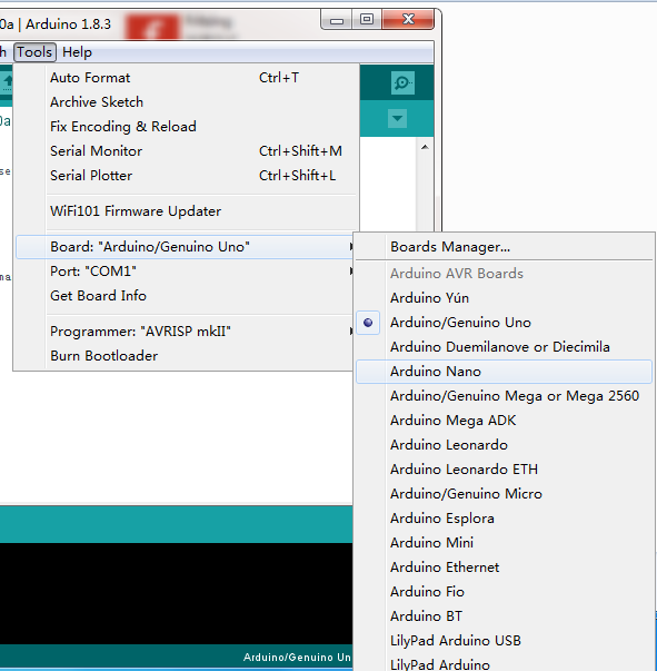
After select the control panel model, select the serial port location and the serial port of the author is COM3:

First, copy the program:
ARDUINO code copy printing
int ledPin = 5; / / set the digital IO pin that controls the LED
void setup ()
{
pinMode (ledPin, OUTPUT); / / set the mode of digital IO port,
}
void loop ()
{
digitalWrite (ledPin, HIGH); / / set PIN5 pin for HIGH = about 5V
delay (2000);
/ / set the delay time, 2000 = 2 seconds
digitalWrite (ledPin, LOW); / / set PIN5 feet for LOW = 0V
delay (2000); / / set the delay time, 2000 = 2 seconds
}
After the program is written, click the compile button to compile.
Once compiled, the compiled file size will be displayed, and this compiled program is 940 bytes.

Then download the compiled program to the arduino control board and click the download button.
The download will be prompted

Replace all of the ledpin with XXX, LED still can work, ledpin is just a name defined by itself. It is just easy to identify.

Conclusion:
“int, void, setup” is the system command. “OUTPUT” is the function switch of the system command, and the black text is the variable.
In "int ledpin = 5";
The digital IO pin of the LED is set, and the ledpin is only the name of number 5 digital port, which can be changed to XXX.
For multi-pins IO operation, it is necessary to define the name for each one, which is easy to recognize when the program is complicated.


评论
发表评论